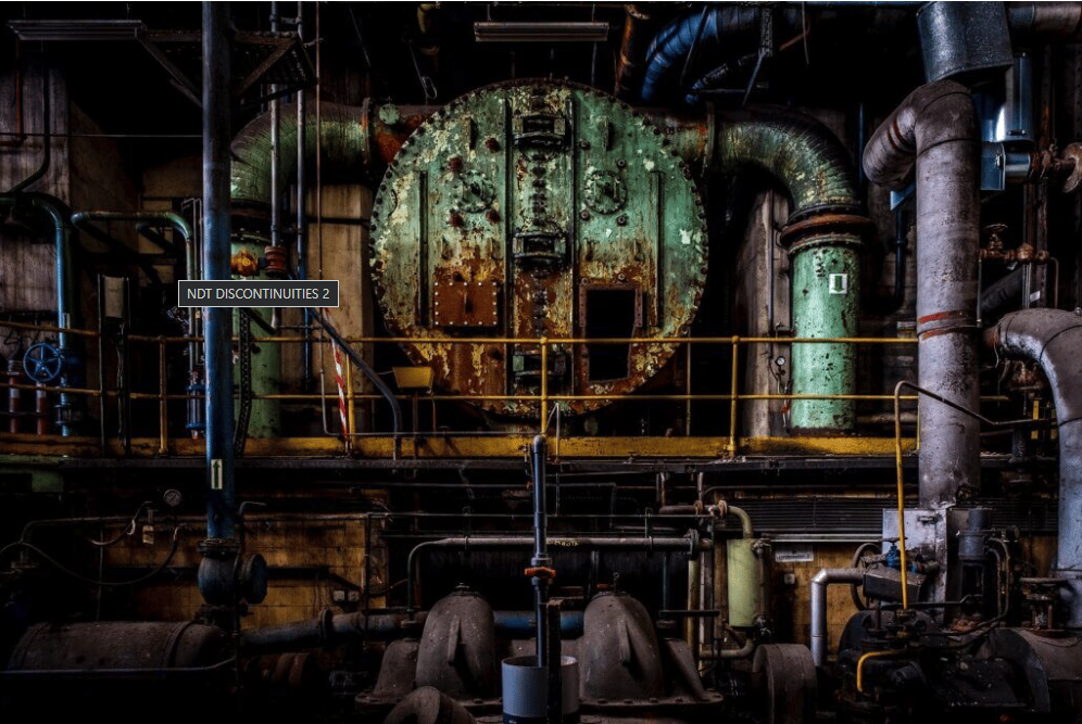
NDT DISCONTINUITIES

Defectology in NDT deals with the defects that affect all the stages of product realization, starting from raw material to finished product. Discontinuities are imperfections in a test object that interfere with the usefulness of the test object. Discontinuities affect the physical properties of the test object and can also affect or hamper the test object’s ability to fulfill the intended purpose and service life.
Discontinuities can be present in a material from the very first stage of its manufacturing if good quality raw materials are not used. when the same material passes through a multiple number of processes shape and size of discontinuities can change.
Non-destructive testing (NDT) is a wide group of analysis techniques used in science and technology industry to evaluate the properties of a material, component or system without causing damage.
To learn more about how NDT began Read our blog:
HISTORY OF NON-DESTRUCTIVE TESTING(NDT)
To learn about need of NDT read our blog:
NEED FOR NON-DESTRUCTIVE TESTING(NDT)
Definitions as per ASME BPVC Sec-V Article 1
- Defect: one or more flaws whose aggregate size, shape, orientation, location, or properties do not meet specified acceptance criteria and are rejectable.
- Discontinuity: a lack of continuity or cohesion; an intentional or unintentional interruption in the physical structure or configuration of a material or component.
- Flaw: an imperfection or discontinuity that may be detectable by nondestructive testing and is not necessarily rejectable.
- Imperfection: a departure of a quality characteristic from its intended condition.
Discontinuities can be divided into three general categories inherent, processing, and service
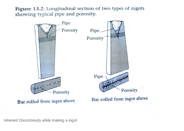
- Inherent Discontinuities are usually formed when the metal molten solidifies. Inherent wrought discontinuities relate to the melting and solidification of the original ingot before it is formed into slabs, blooms, and billets. Inherent cast discontinuities relate to the melting casting and solidification of a cast article. Usually caused by inherent variables such as inadequate feeding, gating, and excessive pouring temperature and entrapped gasses.
- Processing discontinuities are usually related to the various manufacturing processes such as machining, forming, extruding, rolling, welding, heat treatment and plating,
- Service discontinuities are related to the various service conditions such as stress, corrosion, fatigue, erosion.
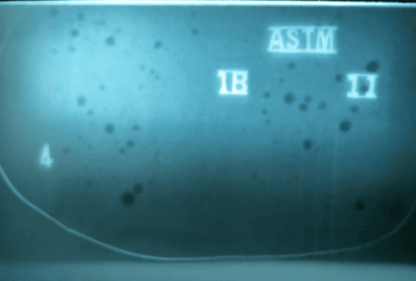
Inherent discontinuities found in the ingot are inclusions, blowholes, pipe, and segregations.
- Nonmetallic inclusions such as slag, oxides, and sulfides are present in the original ingot.
- Blowholes (pores) are formed by gas which is insoluble in the molten metal and is trapped when the metal solidifies.
- Pipe is a discontinuity in the center of the ingot caused by internal shrinkage during solidification.
- Segregations occur when the distribution of the various elements is not uniform throughout the ingot. This condition is called banding.
Typical inherent discontinuities found in castings
- Cold Shut: A cold shut is caused when molten metal is poured over solidified metal.
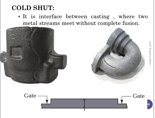
https://slideplayer.com/slide/5732233/
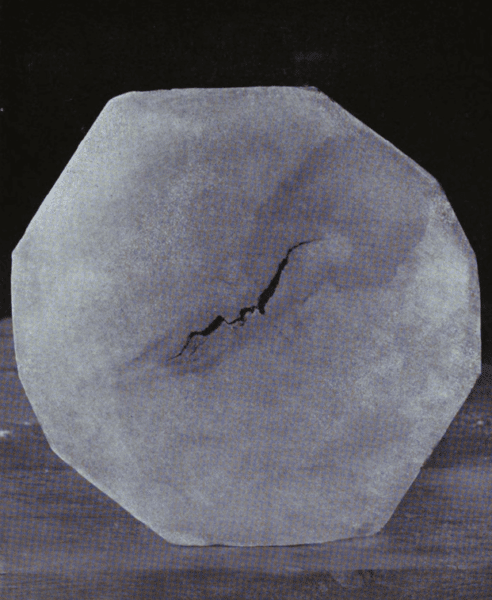
- Hot tears (shrinkage cracks) occur when there is unequal shrinkage between light and heavy sections as shown below
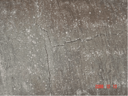
http://ccmcotulsa.com/visible-defects-hot-tears/
- Shrinkage cavities are usually caused by lacking of enough molten metal to fill the space created by shrinkage, similar to the pipe in the ingot.
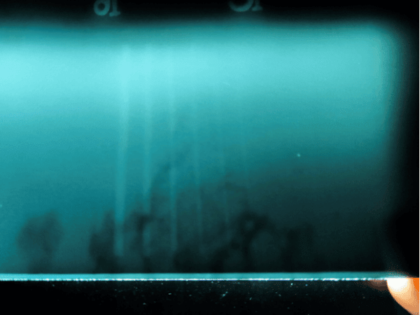
- Micro shrinkage is usually many small subsurface holes that appear at the gate of the casting. It can also occur when the molten metal must flow from a thin section into a thicker section of a casting.
- Blowholes are small holes at the surface of the casting caused by gas which comes from the mold itself many molds are made of sand and when the molten metal comes into contact with the mold the water in the sand is released as steam.
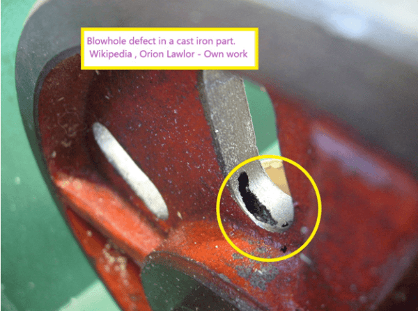
Wikipedia
- Porosity is caused by entrapped gas porosity is usually subsurface but can occur on the surface depending on the design of the mold.
Processing discontinuities
Processing discontinuities are those found or produced by the forming or fabrication operations including rolling, forging, welding, machining, grinding, and heat-treating.
When an ingot is further processed into slabs, blooms, and billets, it is possible for the above discontinuities to change size and shape.
Depending on the type of processing and the original type of discontinuity, the discontinuities after rolling and forming are
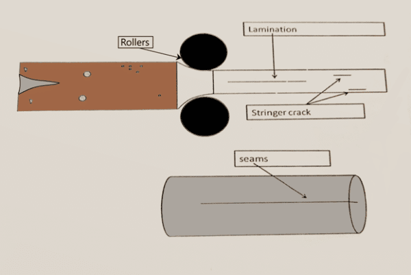
- Laminations: when a billet is flattened or spread out, discontinuities like pipe porosity and nonmetallic inclusions may cause a lamination.
- Stringers: during the rolling process the nonmetallic inclusions are squeezed out into longer and thinner discontinuities called stringers.
- Seams: surface irregularities can cause seams during the rolling process. They are caused by folding of metal due to improper rolling, a crack in a billet, forming of billets into rectangular bars.
Grinding crack is a processing type discontinuity caused by stresses which are built up from excess heat created between a grinding wheel and metal.
Forging discontinuities occur when metal is hammered or pressed into shape usually while the metal is very hot. Forged part gains strength due to the grain flow taking the shape of the die.
A forging lap is caused by folding of the metal on the surface of the forging usually when some of the forging metal is squeezed out between the two dies.
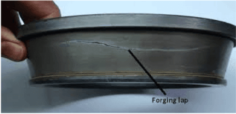
PC: Anveshan, IIT BHU Varanasi
A forging burst is a rupture caused by forging at improper temperatures bursts that may be either internal or open to the surface.
Welding Discontinuities:
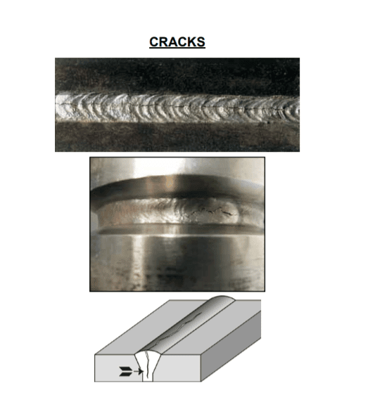
Cold cracking (under bead or delayed cracking): cold cracking is a form of hydrogen-induced cracking that appears in the heat-affected zone or weld metal of low alloy and hardenable carbon steels. The principle factors contributing to cold cracking are the presence of atomic hydrogen. Sources of atomic hydrogen include moisture in the electrode covering, shielding gas or base metal surface as well as contamination of the filler or base metal by a hydrocarbon (oil or grease)
Hot cracking: occurs at elevated temperatures.
Solidification cracking: it occurs near the solidification temperature of the weld metal and is caused by the presence of low melting point constituents typically iron sulfides that segregate to the weld metal dendrite surfaces during the liquid – to – solid transformation processes.
Welders_Visual_Inspection_Handbook-2013_WEB.pdf
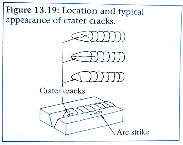
Centreline hot crack is a crack seen following the longitudinal centerline of the deposited weld bead and crater crack occurs in the crater formed at the termination of a weld pass are frequently observed type of solidification cracking.
Liquation cracking or hot tearing occurs in the heat-affected zone of a weld when the temperature in that region results in the results liquation of low melting points constituents.
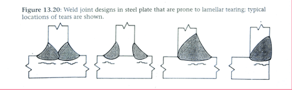
Lamellar tearing: a lamellar tearing is a base metal crack that occurs in plates and shapes of rolled steel exhibiting high nonmetallic inclusion content. These inclusions are rolled flat in the steel plate manufacturing process, severely reducing strength and ductility in the through-thickness direction. When the shrinkage stresses induced by weld solidification are imposed in that direction on the base metal plate, separation of the metal at the flattened inclusions might occur, as may shearing between those lamellar planes resulting in a terraced fracture. It can be readily detectable by magnetic particle testing.
Lack of Fusion/ Incomplete Fusion: Lack of fusion occurs when some portion of the weld filler metal fails to coalesce with the adjacent base metal or the weld metal from a previous pass. In welding processes that use no filler metal, lack of fusion refers to complete coalescence between the two base metal components being joined.
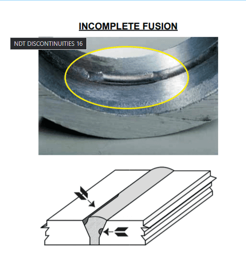
Welders_Visual_Inspection_Handbook-2013_WEB.pdf
Lack of penetration / Incomplete penetration: it is inadequate penetration of the weld joint root by the weld metal. The condition can result from a number of incorrect parameters like low amperage, using oversized electrode, improper arc manipulation, and inadequate pre weld cleaning.
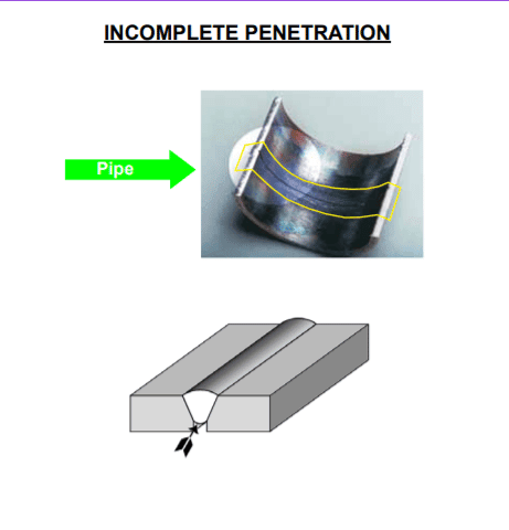
Welders_Visual_Inspection_Handbook-2013_WEB.pdf
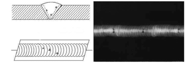
Porosity: Porosity is composed of cavities or pores that form when some constituent within the molten weld metal vaporizes and forms a small pocket of gas that is entrapped when the weld solidifies. The pores can take a variety of shapes and sizes although they are usually spherical. However, one type of elongated pore is often called elongated porosity. The distribution of porosity within the weld metal may be clustered or linear.
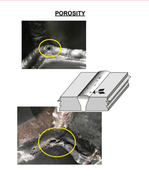
Welders_Visual_Inspection_Handbook-2013_WEB.pdf
Slag Inclusions: Many weld processes use flux shielding, including shielded metal arc welding (SMAW), submerged arc welding (SAW), and flux-cored arc welding (FCAW). Welds produced by these methods are particularly susceptible to discontinuities known as slag inclusions. Slag is entrapped in the weld metal during solidification if it is unable to float out while the pool is still liquid.
Tungsten inclusions are found in the weld metal deposited by the gas tungsten arc welding (GTAW) process and are usually the result of the molten weld pool or the filler metal to come in contact with the tip of the tungsten electrode.
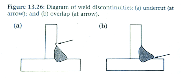
Undercut: undercut occurs at the toe of a weld when the base metal thickness is reduced. Essentially a narrow crevice is formed in the base metal, paralleling the weld toe and immediately adjacent to it. It lessens joint strength in the static sense by reducing the base metal section thickness. Also creates a stress concentration that reduces the impact, fatigue, and low-temperature properties of the joint.
Overlap: overlap is the protrusion of weld metal over the weld toe, producing a form of the lack of fusion that creates a sharp mechanical notch or stress concentration.
Service Discontinuities:
When we manufacture a product making sure it is free from any defect doesn’t mean that the product will last till eternity. Everything has its service life. A product’s service life is its period of use in service. The life expectancy of a component is dependent on its service environment both chemical and mechanical, the quality on its maintenance, and the appropriateness of its design.
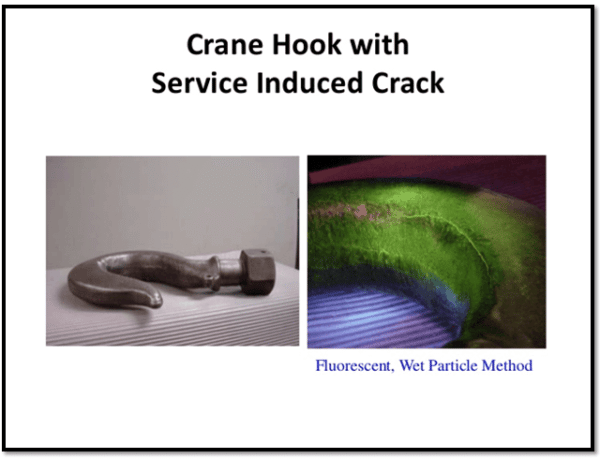
Articles which may develop defects due to metal fatigue are considered extremely critical and demand close attention.
Fatigue cracks are service type discontinuities that are usually open to the surface where they start from stress concentration points. Fatigue cracks are possible only after the part is placed into service but may be the result of porosity, inclusions, or other discontinuities in a highly stresses metal part.
PC:Hareesha N Gowda, Dayananda Sagar College of Engg, Bangalore – Slideshare
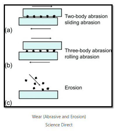
Abrasive wear occurs when a certain material scratches or gouges a softer surface. It has been estimated that abrasion is responsible for 50% of all wear-related failures. A typical example of abrasive wear is the damage of crankshaft journals in reciprocating compressors. Hard dirt particles will break through the lubricant film and cut or scratch the journal’s comparatively softer surface. Wear, or the undesired removal of material from rubbing surfaces, causes many surface failures.
Science Direct
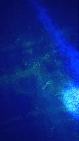
Corrosion is a natural process that converts a refined metal into a more chemically stable form such as oxide, hydroxide, or sulfide. It is the gradual destruction of materials by chemical and/or electrochemical reaction with their environment. Corrosion failure is a material failure related to corrosion. Studies of failure analysis are particularly useful in the chemical processing, refining, oil & gas, and pulp & paper industries.
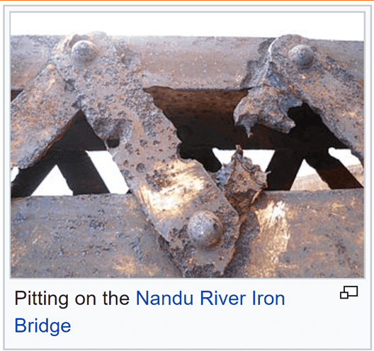
Pitting corrosion, or pitting, is a form of extremely localized corrosion that leads to the creation of small holes in the metal. The driving power for pitting corrosion is the depassivation of a small area, which becomes anodic while an unknown but potentially vast area becomes cathodic, leading to very localized galvanic corrosion. The corrosion penetrates the mass of the metal, with a limited diffusion of ions.
Creep: In materials science, creep (sometimes called cold flow) is the tendency of a solid material to move slowly or deform permanently under the influence of persistent mechanical stresses. It can occur as a result of long-term exposure to high levels of stress that are still below the yield strength of the material. Creep is more severe in materials that are subjected to heat for long periods and generally increases as they near their melting point.
Erosive wear (or erosion) occurs when particles in a fluid or other carrier slide and roll at relatively high velocity against a surface. Individually, each particle removed is insignificant, but a large number of particles removed over a long period of time can produce staggering degrees of erosion.
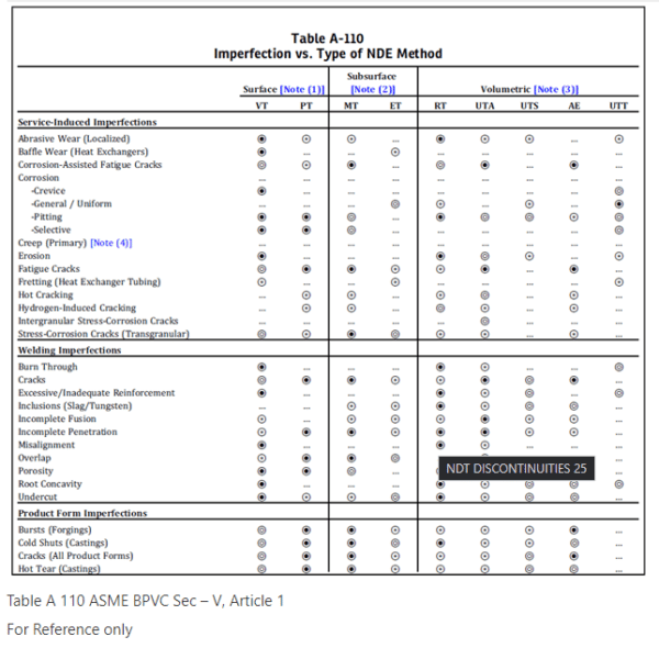
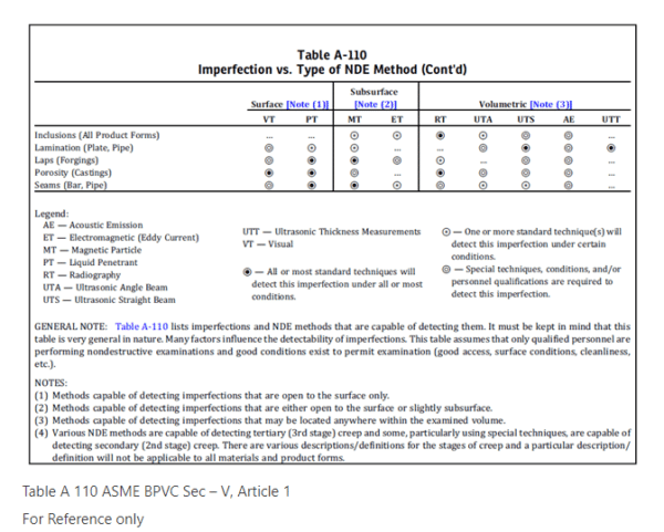
Table A-110 of ASME BPVC Sec-V, Article 1 lists common imperfections and the NDE methods that are generally capable of detecting them.
CAUTION: Table A-110 should be regarded for general guidance only and not as a basis for requiring or prohibiting a particular type of NDE method for a specific application. For example, material and product form are factors that could result in differences from the degree of effectiveness implied in the table. For service-induced imperfections, accessibility and other conditions at the examination location are also significant factors that must be considered in selecting a particular NDE method.
In addition, Table A-110 must not be considered to be all-inclusive; there are several NDE methods/techniques and imperfections not listed in the table. The user must consider all applicable conditions when selecting NDE methods for a specific application.
Disclaimer
We have tried to cover basic types of discontinuities in the general processes. However, there are more discontinuities process-specific and code specific which we have not covered in this article. we will try to cover them in our coming articles.
References :
- PTP Classroom Training Books.
- ASNT RT Lecture Guide.
- ASME BPVC Sec-V
- Wikipedia
- Science direct
- Welders_Visual_Inspection_Handbook-2013_WEB.pdf
- Slide Share
- Erosive wear – Tec Eurolabwww.tec-eurolab.com